Integrating Large Format Radiographic Technology
By Jeff Carter, DDS
Hello and welcome to our new column focus for Dental Office. In an effort to assist you with integrating the latest equipment and technology into your existing, remodeled or new facility, our article series will address selected unit infrastructure requirements. Requirements such as utility connections, spatial consumption, cabinetry considerations, access strategy and optimal facility positioning to maximize unit effectiveness will be addressed. Our article series will focus less on which manufacturers’ products may or may not be the best purchase option for your situation. We will leave that distinction to the CRA and others who assist us in evaluating performance and durability.
The diagnostic value of large format radiographic technologies in dentistry has been and will continue to be profound. Images created by panoramic units, panoramic units with cephalometric attachments, panoramic units with tomographic capabilities, and the latest sensation — cone beam technology sectioning scans — provide clinicians incomparable diagnostic data. The “big picture” (literally) radiographic data that cannot be secured through intraoral periapical and bitewing use radiographs only.
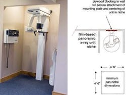
As terrific as the advent of digital radiographic images has been, this advance has created integration challenges. Film-based or non-digital panoramic units, the previous standard for most general practice facilities utilizing large format images, typically required a 4’ 6” x 4’ 6” niche directly off a corridor or at the end of a corridor to house the unit. Film-based pan units require only a line voltage connection. The typical pan MEP specification is a load of 15 amps connected to a dedicated circuit with a 20 amp breaker at the electrical panel. All radiographic equipment manufacturers specify dedicated circuitry for their units to prevent power fluctuations impacting X-ray pulse generation. (RE: Image one). Image one displays an older film-based panoramic unit mounted in the minimum-sized niche adjacent to the operatory corridor for this facility. Regulations vary from state to state and at present it is less likely regulators will allow the transformer / activator box with dangling activator cord in the niche alongside the unit as shown here.
Non-digital panoramic-cephalometric units are used more frequently by specialists and general practitioners providing orthodontic treatment with the need to capture lateral head images for tracings and other diagnostic information. The minimum pan-ceph niche is 7’6” in width and 4’ 6” in depth (RE: Image two). Pan-ceph units also require connection to dedicated 20 amp circuit and proper blocking.
For those of you converting to digital radiography through the use of an older film-based pan or pan-ceph unit coupled with a phosphor scanning plate system, the pan niche or pan-ceph niche requirements described above are still applicable. For efficiency, positioning the phosphor plate scanning unit and associated workstation near the pan or pan-ceph unit is a must. (RE: Image three). Image three displays two examples of phosphor plate scanning areas immediately adjacent to pan units and the associated workstations that provide network access to captured images once the scanning process is complete.
If you are contemplating designing, constructing and equipping a new facility, I would encourage you to research the purchase of a direct capture CCD pan or pan-ceph unit, even if you have made the decision to purchase a phosphor plate scanning system for intraoral images. The cost differential between a direct capture CCD panoramic unit and the non-digital counterpart is in the range of $8,000 to $10,000. The cost addition to include large format scanning capability to a phosphor plate scanning unit is approximately $8,000 to $10,000. As a result, I recommend the combination of a phosphor plate scanning system such as Op-Time or Scan-X combined with a direct capture CCD digital panoramic unit or panoramic-cephalometric unit.
Digital pan and pan-ceph units vs. non-digital units utilizing film or phosphor plate scanning systems in my opinion provide:
- Superior image quality
- Less labor intensive protocols with quicker capture and processing of image
- Capability to stop faulty image during capture process, reducing overall radiation exposure to patient. The captured image is rendered and displayed on the associated workstation monitor screen as the panoramic unit progresses.
The integration of a direct capture CCD pan or pan-ceph unit is more challenging in a retrofit than a non-digital unit. In new design and construction facilities, we can optimize the placement of a digital pan or pan-ceph unit. (RE: Image four). Digital pan and pan-ceph units require the following:
- line voltage dedicated 20 amp outlet
- plywood blocking to secure and center unit in niche
- associated networked workstation to receive data cable connection to pan or pan-ceph unit. (data cable typically connects to proprietary capture board in CPU)
- pan niche minimum dimensions 4’ 6” x 4’ 6”
- pan-ceph niche minimum dimensions 4’ 6” x 7’ 6”
- associated workstation positioned to allow viewing of monitor screen during capture process to allow termination of faulty image capture
I would not recommend enclosing the pan or pan-ceph unit in a room with a door unless you happen to have a large unused space within your current facility that can be utilized without compromising other areas. To enclose a pan unit in a room with a door and satisfy ADA (American with Disabilities Act) requirements would necessitate a room with dimensions in the range of 8’ x 9’ or larger depending on the precise configuration.
Intra-Office Positioning Of Large Format Radiographic Units:
Capturing of radiographic images is a clinical activity. In new design and construction facilities we compartmentalize facilities into three zones of activity. Those three distinct zones (PUBLIC – PRIVATE - CLINICAL) segregate and associate similar activities to lower stress and increase efficiency. Large format radiographic units are typically placed at the transition node between the PUBLIC and CLINICAL zones. This rationale arises from the utilization flow of the unit. For example, a patient is retrieved from the waiting area and escorted to the pan unit. An image is captured, the patient is escorted to the front desk and then released. The patient returns at a later date for a consultation appointment. In this scenario, it would not have been efficient for the staff and patient to traverse the extent of the clinical area to access a pan.
Cone Beam Technology:
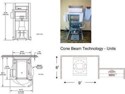
Cone beam technology has provided a revolutionary advance in large format radiographic techniques. Cost implications will limit the use of this technology by solo general practitioners for a time. Specialists and group practices will be the first beneficiaries of integrating this option. Dental Economics presented a terrific compilation of cone beam technology options. My concern after reviewing many of the manufacturers’ unit options is the lack of standardization in unit sizing. Pan and pan-ceph units regardless of manufacturer have maintained standardized “footprints” that allow us to plan for and design consistently sized niches. This allows shopping time during the design process to select a particular unit. With units of varying sizes, it often requires selecting the unit in advance to allow optimization of the integration space. (RE: Image five). In image five, this manufacturer’s cone beam technology unit has a larger footprint than the traditional pan unit. My recommendation would be when integrating cone beam technology units to allow 36” either side of the unit to prevent the niche enclosure from feeling claustrophobic to the patient. The cone beam image sectioning capture process would typically be a longer process than traditional pan and pan-ceph image taking, presenting the opportunity to increase patient anxiety during the process.
If you are currently researching the viability of cone beam technology in your current or new facility, here is additional information you may find useful. A new report was released this week by the New England Journal of Medicine identifying new dangers of medical CT scans. Specifically, the research shows that unnecessary or overused patient CT scans have been found to cause an increased risk of cancer. We would all agree that is an obvious conclusion whenever patients are exposed to additional radiation.
Due to the specifics of the dental cone beam technology units and reduced areas scanned, dental CT scans produce approximately 1/100 the radiation exposure of the average medical CT scan.
Our thoughts and prayers go out to Mary Govoni for the recent loss of her husband, Lenny. Mary has made countless contributions to dentistry over the years for which we are all thankful.
Warm regards,
Jeff
A Biographical Sketch
Dr. Jeff Carter is co-owner of the Practice Design Group, based in Austin, Tex. PDG specializes in providing architectural, interior design and equipment, and technology integration services to dentists nationwide. Dr. Carter may be contacted by phone at (512) 295-2224, by e-mail at [email protected], or by visiting PDG’s Web site at www.practicedesigngroup.com.


